- 您现在的位置:买卖IC网 > Sheet目录110 > SBR30A100CTB-13 (Diodes Inc)DIODE SBR 30A 100V D2PAK
SBR30A100CTB
Document number: DS31721 Rev. 5 - 2
2 of 4
www.diodes.com
July 2011
? Diodes Incorporated
SBR30A100CTB
SBR is a registered trademark of Diodes Incorporated.
Maximum Ratings
@TA
= 25°C unless otherwise specified
Single phase, half wave, 60Hz, resistive or inductive load.
For capacitance load, derate current by 20%.
Characteristic Symbol Value Unit
Peak Repetitive Reverse Voltage
Working Peak Reverse Voltage
DC Blocking Voltage
VRRM
VRWM
VRM
100 V
Average Rectified Output Current @ TC
= 150oC Per Leg
Total
IO
15
30
A
Non-Repetitive Peak Forward Surge Current 8.3ms
Single Half Sine-Wave Superimposed on Rated Load
IFSM
180 A
Thermal Characteristics
Characteristic Symbol Value Unit
Maximum Thermal Resistance (per leg)
Thermal Resistance Junction to Case (Note 4)
RθJC
3
°C/W
Operating and Storage Temperature Range
TJ, TSTG
-65 to +150 oC
Electrical Characteristics
@TA
= 25°C unless otherwise specified
Characteristic Symbol Min Typ Max Unit Test Condition
Forward Voltage Drop (per leg)
VF
-
0.78
-
0.85
0.70
V
IF
= 15A, T
J
= 25oC
IF
= 15A, T
J
= 125oC
Leakage Current (Note 5)
IR
-
-
-
100
10
μA
mA
VR
= 100V, T
J
= 25oC
VR
= 100V, T
J
= 125oC
Notes: 4. FR-4 PCB, 2 oz. Copper, minimum recommended pad layout per http://www.diodes.com.
5. Short duration pulse test used to minimize self-heating effect.
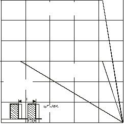
0
25 50 75 100 125
10
R = 16°C/WθJA
20
30
150
I AVERAGE FORWARD CURRENT (A)
F(AV),
T , AMBIENT TEMPERATURE ( C)A
°
Fig. 1 Forward Current Derating Curve
Per Element
R = RθθJA JC
Total Device
R = RθθJA JC
Per Element
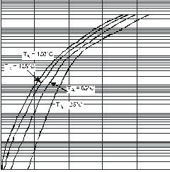
25
15
5
0.0001
0 200 400 600 800 1,000
0.001
0.01
0.1
1
10
100
Fig. 2 Typical Forward Characteristics
V , INSTANTANEOUS FORWARD VOLTAGE (mV)F
I , INSTANTANEOUS FORWARD CURRENT (A)
F


发布紧急采购,3分钟左右您将得到回复。
相关PDF资料
SBR30A100CTE
DIODE ARRAY SBR 100V 15A TO262
SBR30A100CT
DIODE SBR 30A 100V TO220-3
SBR30A120CT
DIODE SBR 30A 120V TO220-3
SBR30A150CT
DIODE SBR 30A 150V TO220-3
SBR30A40CTFP
DIODE SBR 30A 40V TO220-3
SBR30A45CTB
DIODE SBR 45V 30A TO263
SBR30A45CTFP
DIODE SBR 30A 45V TO220-3
SBR30A60CTB-13
DIODE ARRAY 60V 15A D2PAK
相关代理商/技术参数
SBR30A100CTE
功能描述:DIODE ARRAY SBR 100V 15A TO262 RoHS:是 类别:分离式半导体产品 >> 二极管,整流器 - 阵列 系列:SBR® 其它有关文件:STTH10LCD06C View All Specifications 标准包装:1,000 系列:- 电压 - 在 If 时为正向 (Vf)(最大):2V @ 5A 电流 - 在 Vr 时反向漏电:1µA @ 600V 电流 - 平均整流 (Io)(每个二极管):5A 电压 - (Vr)(最大):600V 反向恢复时间(trr):50ns 二极管类型:标准 速度:快速恢复 = 200mA(Io) 二极管配置:1 对共阴极 安装类型:表面贴装 封装/外壳:TO-263-3,D²Pak(2 引线+接片),TO-263AB 供应商设备封装:D2PAK 包装:带卷 (TR) 产品目录页面:1553 (CN2011-ZH PDF) 其它名称:497-10107-2
SBR30A100CTFP
功能描述:肖特基二极管与整流器 30A 100V Low VF RoHS:否 制造商:Skyworks Solutions, Inc. 产品:Schottky Diodes 峰值反向电压:2 V 正向连续电流:50 mA 最大浪涌电流: 配置:Crossover Quad 恢复时间: 正向电压下降:370 mV 最大反向漏泄电流: 最大功率耗散:75 mW 工作温度范围:- 65 C to + 150 C 安装风格:SMD/SMT 封装 / 箱体:SOT-143 封装:Reel
SBR30A100CT-G
制造商:Diodes Incorporated 功能描述:30A SBR SUPER BARRIER RECTIFIER
SBR30A100PT
制造商:Diodes Incorporated 功能描述:
SBR30A120CT
功能描述:肖特基二极管与整流器 30A 120V LOW VF RoHS:否 制造商:Skyworks Solutions, Inc. 产品:Schottky Diodes 峰值反向电压:2 V 正向连续电流:50 mA 最大浪涌电流: 配置:Crossover Quad 恢复时间: 正向电压下降:370 mV 最大反向漏泄电流: 最大功率耗散:75 mW 工作温度范围:- 65 C to + 150 C 安装风格:SMD/SMT 封装 / 箱体:SOT-143 封装:Reel
SBR30A120CTFP
功能描述:肖特基二极管与整流器 30A 120V LOW VF RoHS:否 制造商:Skyworks Solutions, Inc. 产品:Schottky Diodes 峰值反向电压:2 V 正向连续电流:50 mA 最大浪涌电流: 配置:Crossover Quad 恢复时间: 正向电压下降:370 mV 最大反向漏泄电流: 最大功率耗散:75 mW 工作温度范围:- 65 C to + 150 C 安装风格:SMD/SMT 封装 / 箱体:SOT-143 封装:Reel
SBR30A150CT
功能描述:肖特基二极管与整流器 30A 150V RoHS:否 制造商:Skyworks Solutions, Inc. 产品:Schottky Diodes 峰值反向电压:2 V 正向连续电流:50 mA 最大浪涌电流: 配置:Crossover Quad 恢复时间: 正向电压下降:370 mV 最大反向漏泄电流: 最大功率耗散:75 mW 工作温度范围:- 65 C to + 150 C 安装风格:SMD/SMT 封装 / 箱体:SOT-143 封装:Reel
SBR30A150CTFP
功能描述:肖特基二极管与整流器 30A 150V RoHS:否 制造商:Skyworks Solutions, Inc. 产品:Schottky Diodes 峰值反向电压:2 V 正向连续电流:50 mA 最大浪涌电流: 配置:Crossover Quad 恢复时间: 正向电压下降:370 mV 最大反向漏泄电流: 最大功率耗散:75 mW 工作温度范围:- 65 C to + 150 C 安装风格:SMD/SMT 封装 / 箱体:SOT-143 封装:Reel
